AerialView
Want to discover a new, easy, and affordable way to view and analyze your antenna patterns?
Do you work with antenna data? Is it important to you to visualize antenna patterns? Would you be in interested in software that is easy to learn, easy to use, and can save you valuable time? If you answered yes to any of these questions you should try AerialView.
Powerful and affordable antenna visualization, analysis, and editing tool
AerialView is a fast, highly interactive software application designed for engineers, students, and others interested in the analysis and visualization of antenna radiation patterns. With AerialView’s intuitive user interface you will be able to visualize and analyze antenna patterns with minimal start up time. Once installed, you can easily sort, find, view (in 2D or 3D), compare, edit, analyze, and manage all your antenna patterns. AerialView provides many features and options. It is highly customizable, so you can tailor options to adapt to your specific needs. Analysis tools enable you to generate theoretical patterns, view pattern distortion caused by structures, or view coverage profiles for a patterns.
Included with the installation
Sample antennas — AerialView includes a library of sample antenna patterns in AerialView format so that you can get started immediately. AerialView also supports the import and automatic conversion of a number of popular antenna file formats to AerialView format, as well as information about AerialView’s native file format so that you can convert other antenna pattern files.
Documentation — AerialView includes context sensitive online Help and a printable PDF version of the User’s Guide.
System Requirements
To use AerialView you must meet the following system requirements. – Microsoft® Windows® 2000, Windows XP, Windows Vista, or Windows 7 – A minimum of 50 MB of free disk space for installation. – Display resolution of 1024×768 or better. Contact us to find out more about AerialView.
Features
Visualization
Visualization of 2D & 3D antenna patterns
You can generate 3D patterns from vertical and horizontal pattern data, in either spherical or rectangular coordinate systems.
Once generated, there are many options available for manipulating the display. You can view patterns in 2D or 3D, view results in linear or dB units, or interactively “slice” 3D pattern surfaces to view details. You can easily control the display of colors, grids, labels, and other characteristics. You can even view the same pattern in multiple ways, simultaneously, using multiple views.
Features
Theoretical Patterns
Generation of theoretical patterns
AerialView provides an easy way to generate a number of different theoretical patterns, and enables you to set various input parameters, such as frequency and geometrical dimensions. Once generated, the theoretical patterns can be analyzed just like any pattern.
Features
Interactive Editing
Interactive editing and reformatting capabilities
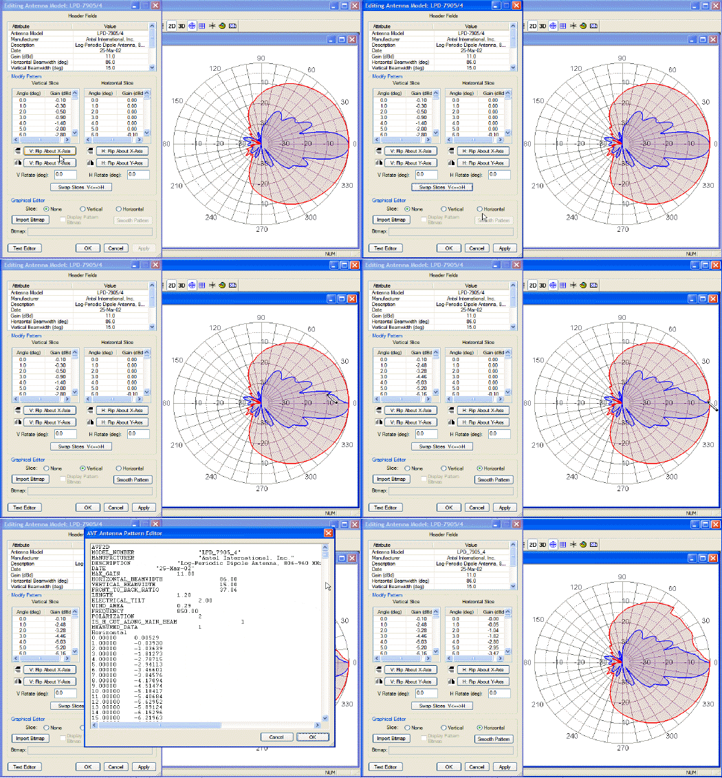
Use AerialView’s Pattern Editor to manipulate antenna pattern data. The Pattern Editor enables you to change individual data points, shift or translate a pattern, or re-shape patterns. You use the Pattern Editor in conjunction with the visual display of the pattern. As you make changes in the Pattern Editor they are immediately updated in the active view. With the included Graphical Editor you can either manipulate data graphically for an exiting pattern, or create a new pattern by tracing a bitmap of an antenna pattern.
Features
Antenna Browser
Browsing and previewing antenna patterns
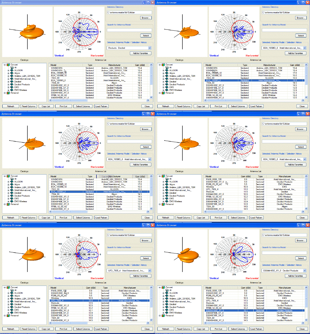
AerialView’s built in antenna browser makes it easy for you to scan through antenna directories and view 2D and 3D “thumbnails” of antenna patterns. You can use the features of the antenna browser to find antennas that meet certain characteristics. Once you find antennas of interest, you can save them to a “Favorites” catalog for easy access.
Features
Antenna Comparisons
Comparison of any two 2D or 3D antenna patterns
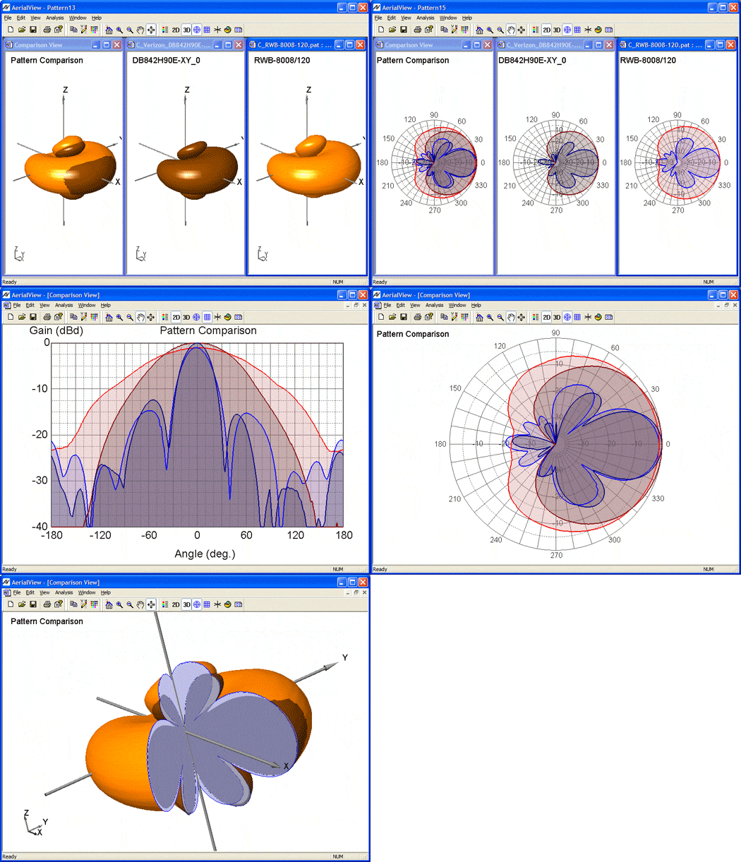
AerialView includes a Comparison Tool that provides a visual way of comparing differences in the shapes of antenna patterns. Patterns can be compared in either 2D or 3D space. Using AerialViews options for customizing the pattern display, and using multiple views, gives you many options for visualizing and presenting the differences between two patterns.
Features
Coverage Analysis
Coverage profile analysis
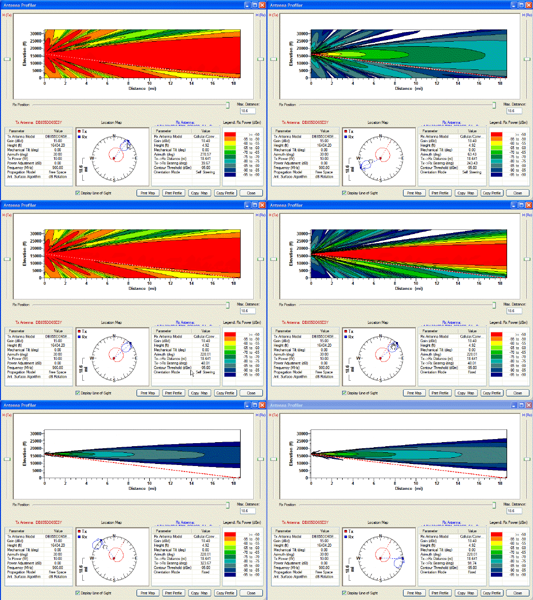
Using the controls in AerialView’s Antenna Profiler you can interactively visualize how an antenna pattern contributes to the shaping of a coverage area. The shaping of the coverage area for a transmitting base station is determined by the details of the antenna pattern in three dimensions, and the characteristics of the transmitter and receiver. The characteristics of the transmitting and receiving antenna can be individually modified, as well as the position and orientation mode (fixed or self steering) of the receiving antenna. The Profiler displays the coverage profile contour as a cross section.
Features
Distortion Analysis
Analysis of distortions caused by supporting structures
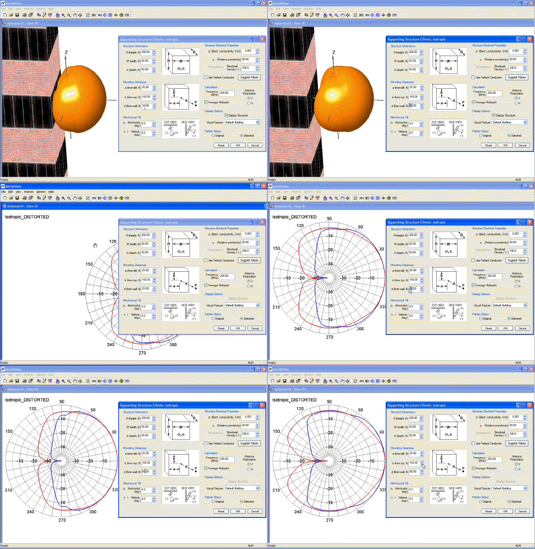
AerialView includes a Supporting Structures Effects tool to analyze how various supporting structures distort an antenna pattern. The tool allows you to modify dimensions for the structures, electrical properties for the supporting structure, and the placement of the antenna mounting location.
You can view the effects of distortion while viewing either a 3D or 2D pattern. The pattern updates as you adjust parameters. The distorted pattern can be saved for use in RF planning tools.
Features
Pattern Properties
Calculation of 2D & 3D pattern properties
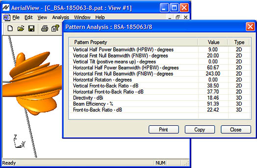
AerialView includes a Pattern Analysis tool that automatically calculates attributes such as horizontal beamwidth, vertical beamwidth, beam efficiency, tilt, and front-to-back ratio. The calculations are carried out with either 2D or 3D pattern data, and provides a convenient way of checking the specifications of a vendor-supplied pattern, or characterizing a theoretical pattern.
Properties update automatically as you select different patterns open in the AerialView desktop.
